
The correct interpretation of load charts is a fundamental skill for crane operators. In New Zealand, where cranes are extensively used across construction, manufacturing, and logistics sectors, this knowledge is not merely beneficial; it is essential for safe operation. Load charts tell operators how much weight a crane can safely lift at various configurations, making them critical safety tools. Misinterpreting these charts can lead to dangerous overloading, potentially causing crane failure, structural damage, injury, or even fatalities.
Understanding the Basics of Load Charts
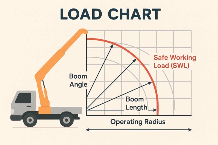
At their core, load charts display the safe working load (SWL) of a crane in relation to its operating radius. The operating radius refers to the horizontal distance from the centre of rotation to the load line. This relationship is fundamental because the further a load extends from the crane’s centre, the less weight the crane can safely manage.
Load charts are typically presented as tables or graphs showing the maximum permitted load at different boom lengths, angles, and radii. These charts are designed specifically for each crane model and configuration, making them unique to the particular equipment being operated.
Key Elements of a Load Chart
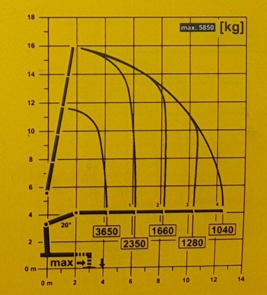
A comprehensive load chart contains several crucial elements that operators must understand. The chart will specify the crane’s maximum lifting capacity in relation to the boom’s length and angle under optimal conditions (e.g. no wind, level ground, etc).
As the boom extends or lowers, the crane’s capacity diminishes significantly. For instance, a crane might be capable of lifting 3650 kilograms at its maximum capacity, but with the boom fully extended horizontally, this could reduce to as little as 1040 kilograms, less than 30 percent of the theoretical maximum.
Operating limitations such as maximum wind speeds, outrigger positions, and ground conditions may also be specified. These conditions must be met for the chart’s values to remain valid.
The Impact of Boom Configuration
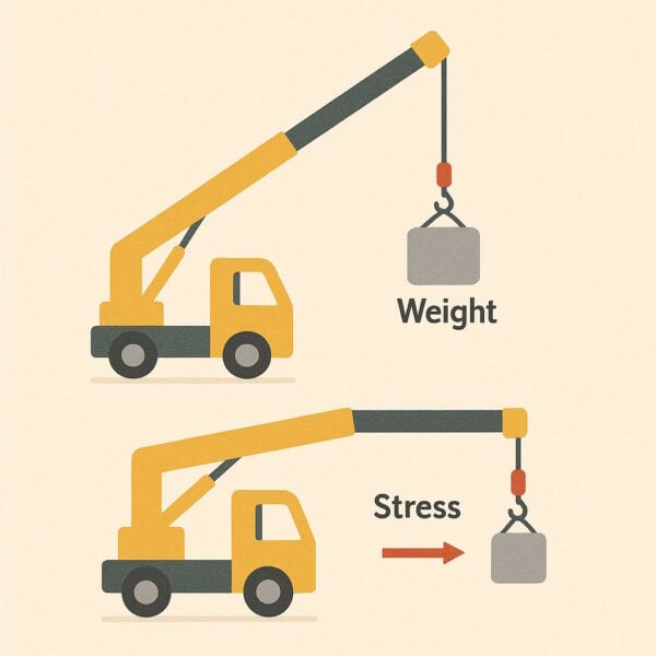
Boom configuration has a dramatic effect on a crane’s lifting capacity. When a boom is extended further out, it creates a lever effect, placing more stress on the crane’s structure. This principle is easily demonstrated: holding a light weight close to your body feels manageable, but extending your arm fully makes the same weight feel much heavier.
Outriggers and Stability
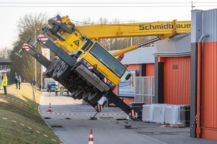
For mobile cranes and truck loader cranes, outriggers (stabilising legs) must be fully extended and properly set to achieve the capacities listed on the load chart. If outriggers are not fully deployed, the chart values become invalid, and the crane’s stability is compromised.
The stability of a crane under static conditions should be such that the rated capacity does not exceed a certain percentage of the tipping load. According to New Zealand regulations, this is typically no more than 78% for stabilised cranes and 66% for free-on-wheels operations.
Multiple Lifting Points and Angles
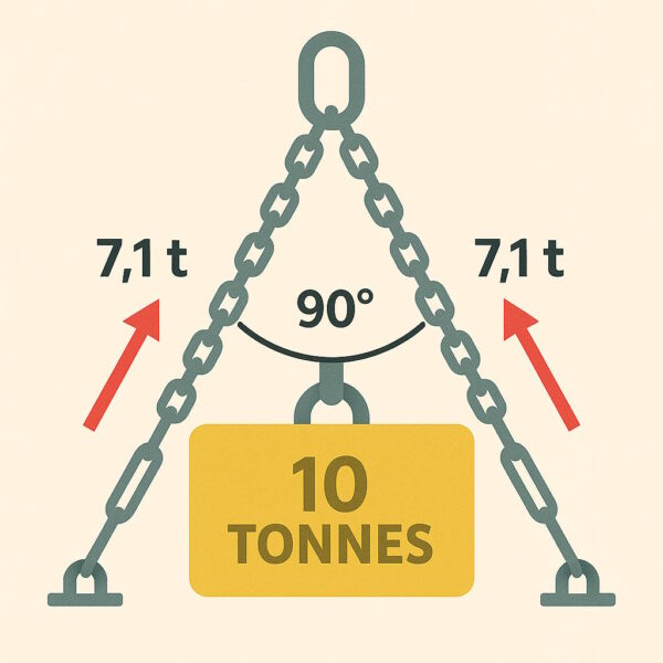
When using multiple lifting points, such as with spreader bars or when employing more than one sling, the load distribution and included angles between slings become critical factors. As the angle between slings increases, so does the force on each sling, potentially exceeding their working load limits.
For example, when two chains each rated for 5 tonnes are arranged at a 90-degree included angle, each chain must support approximately 7.1 tonnes of force for a 10-tonne load – a substantial increase over their intended capacity. Not realising this can lead to chain breakages or damage.
Environmental Considerations
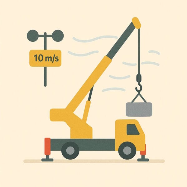
Environmental factors significantly impact the validity of load charts. High winds place additional stress on the crane and load, effectively reducing the safe working load. Similarly, ground conditions affect stability, especially for mobile cranes. Soft or uneven ground can cause outriggers to sink or shift, jeopardising the crane’s stability.
Safe Application in Practice
Practical application of load chart knowledge begins before a lift is attempted. Operators should:
- Determine the weight of the load accurately
- Consider the centre of gravity of irregular loads
- Measure the required boom length and angle
- Check the load chart to verify that the crane can handle the weight at the specified radius
- Ensure all conditions specified on the chart (outrigger extension, etc.) are met
- Apply a safety margin to account for dynamic forces during lifting
If the operating radius exceeds the crane’s capacity, the operator must reposition the crane closer to the load or select a crane with greater capacity.
The Consequences of Misinterpretation
Misinterpreting load charts can have severe consequences. When a crane is overloaded, structural components may fail, the crane may tip over, or the load may drop unexpectedly. These failures often occur without warning, giving operators little time to react.
New Zealand’s Health and Safety at Work Act 2015 places significant responsibility on employers and operators to ensure that equipment is operated safely within its design limitations. This includes ensuring operators are properly trained in load chart interpretation.
Conclusion
Interpreting load charts correctly is an indispensable skill for crane operators and is fundamental to safe lifting operations. These charts are not merely guidelines but critical tools that define the operational limits of crane equipment. Through proper understanding and application of load chart information, operators can make informed decisions that protect themselves, their colleagues, and the public from the significant risks associated with crane operations.
Regular training and assessment in truck loader crane load chart interpretation should be part of every crane operator’s professional development.


Darren has written over 3000 articles about driving and vehicles, plus almost 500 vehicle reviews and numerous driving courses. Connect with him on LinkedIn by clicking the name above